 1
1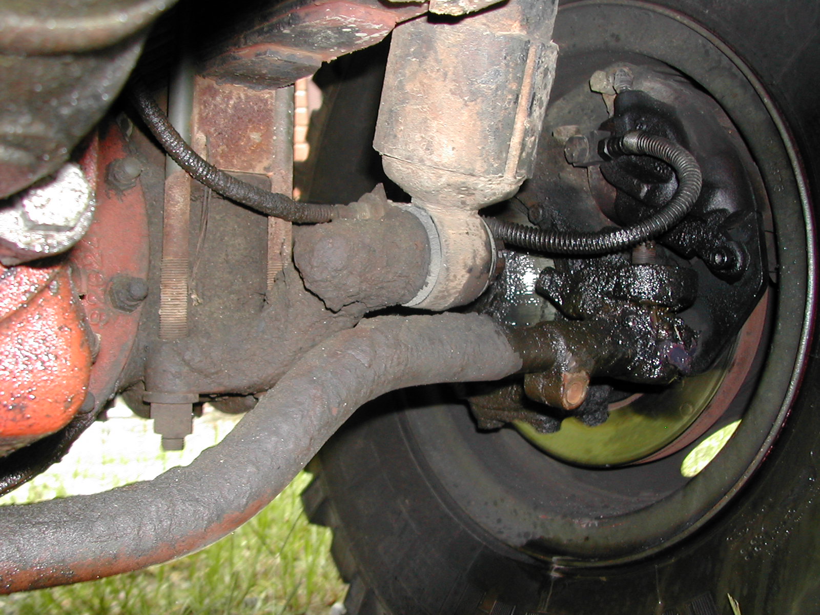 2
2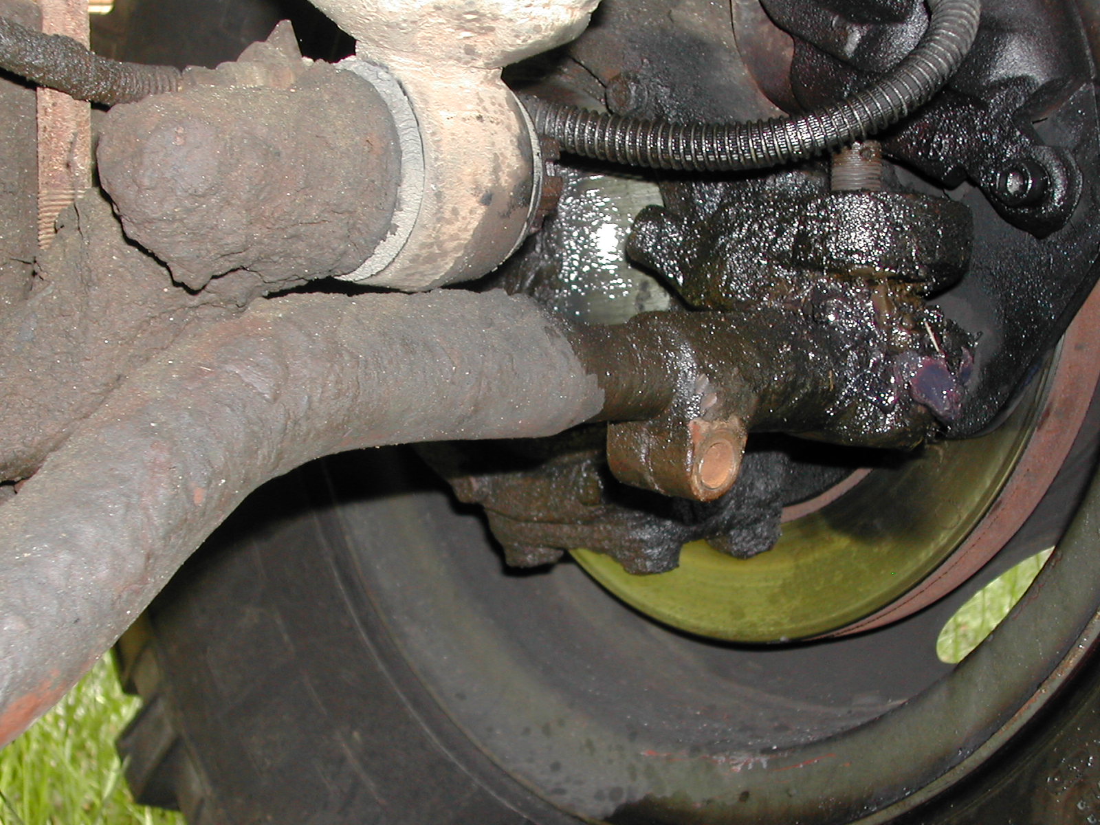 3
3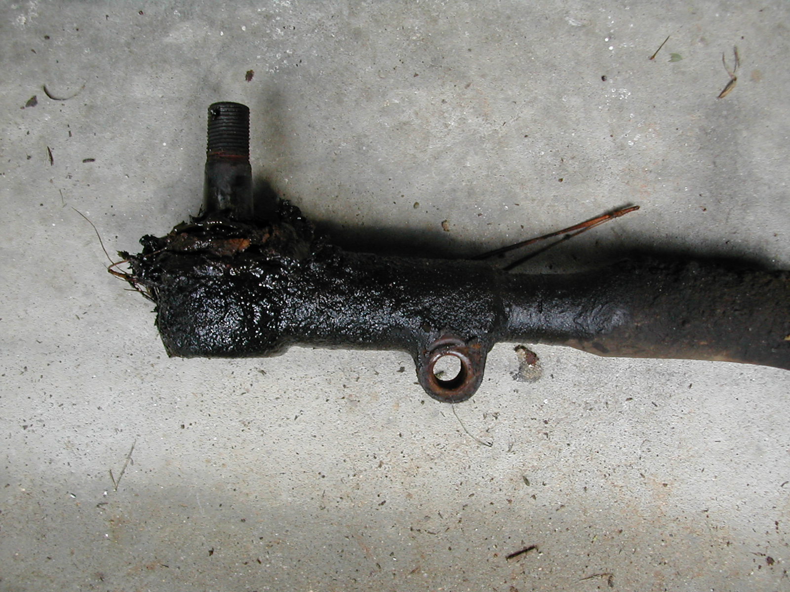 4
4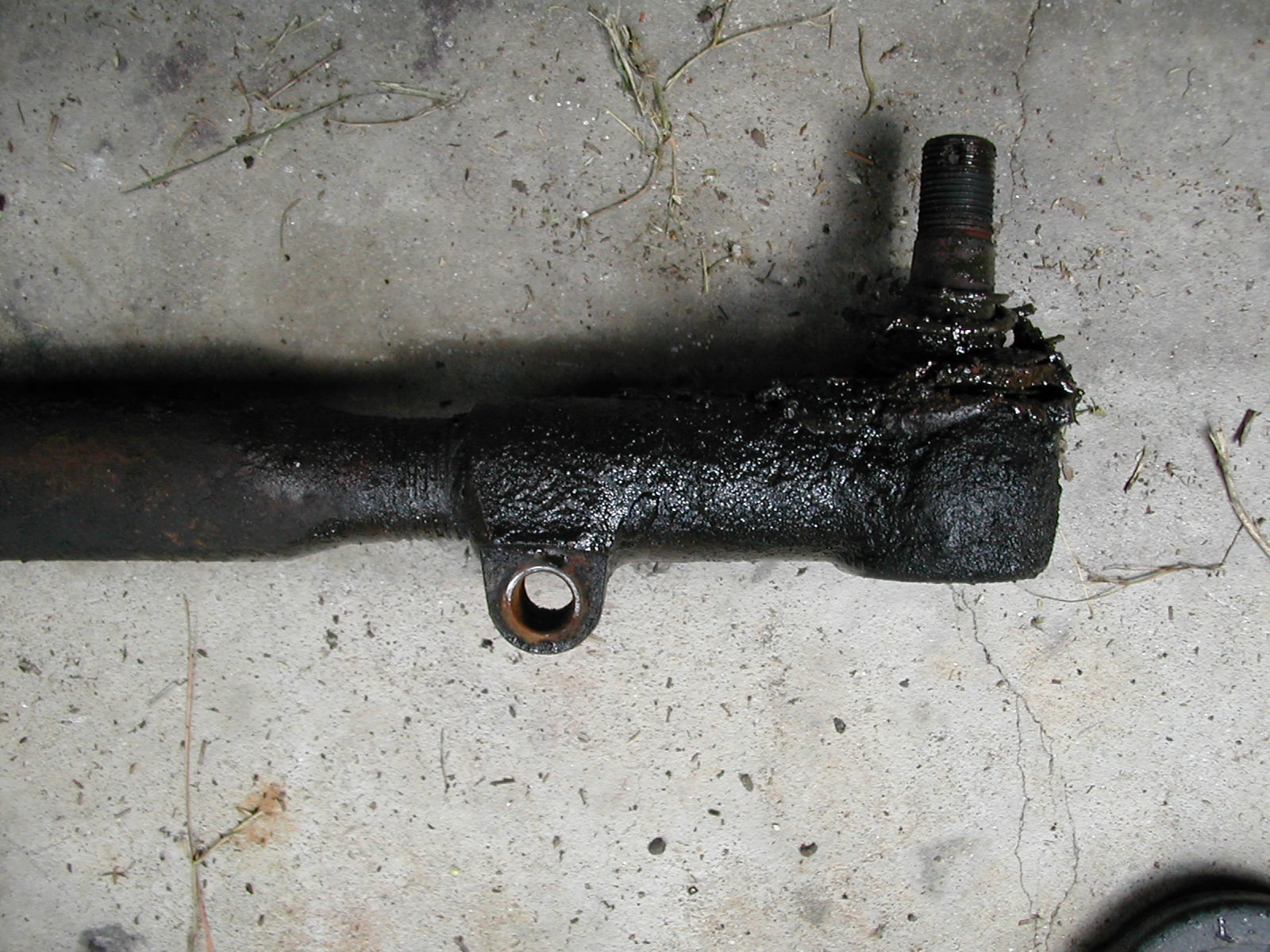 5
5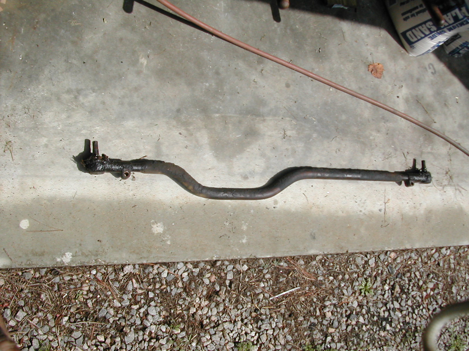 6
6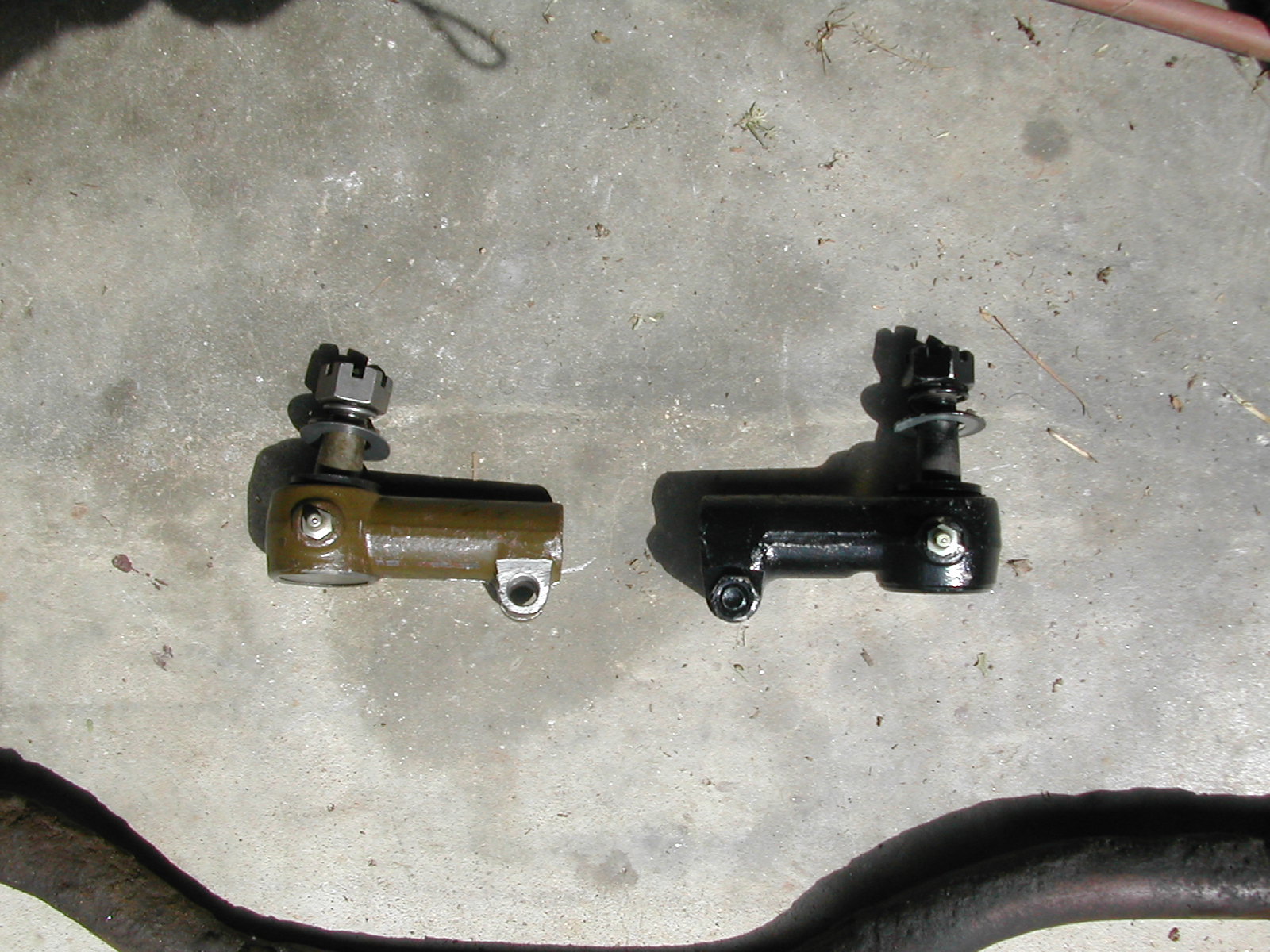 7
7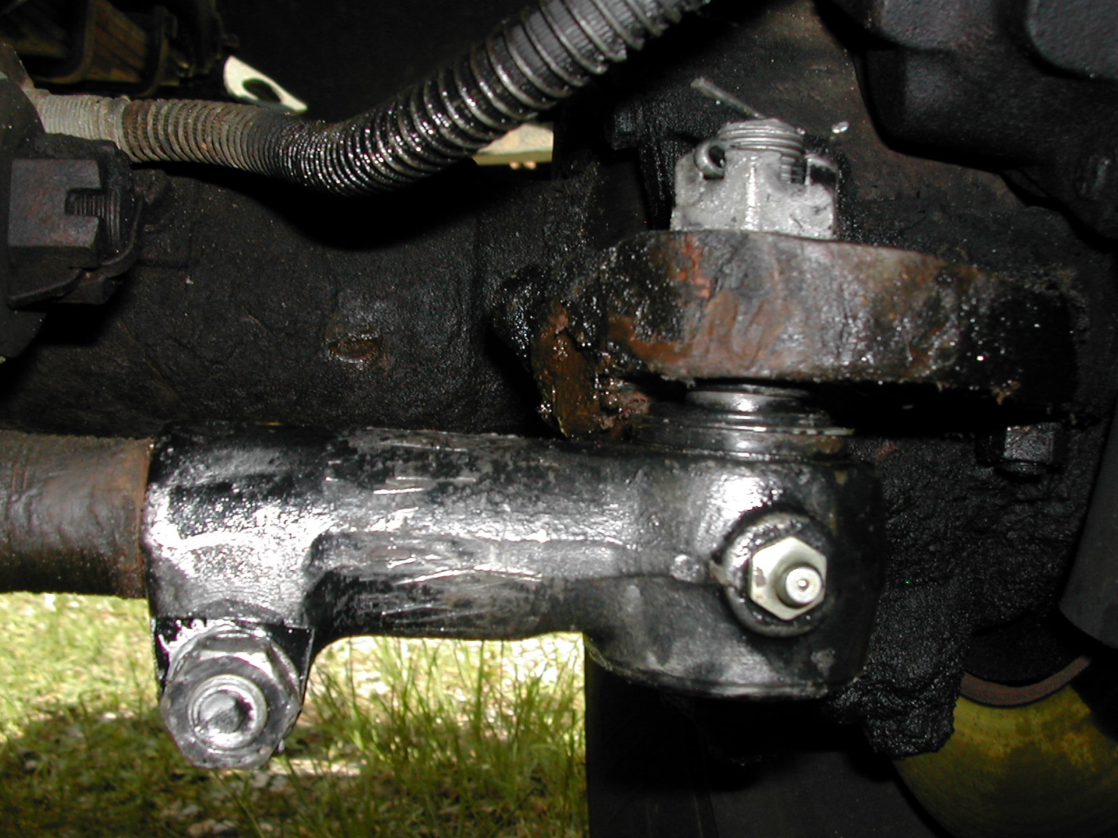 8
8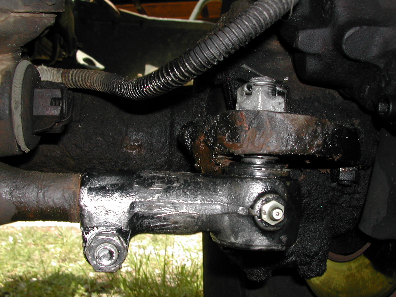 9
9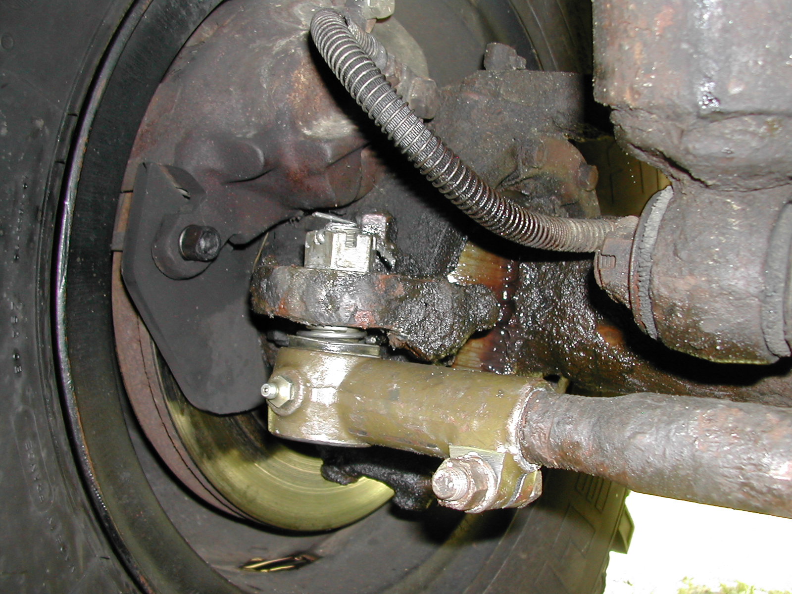 10
10M37 Tie Rod End Replacement
I decided to replace the tie rod ends one Saturday morning since the original ones had
just a bit too much slop in them for me to continue to feel comfortable driving down the
roads at high speeds... I purchased a set of new ends from ABLinn for $40 or so for the
pair. Removal aided by the use of a pickle fork (ball joint separator).
The whole assembly just fell on the ground once I pulled the cotter pins, removed
the bolts, and slid the fork between the tie rod and the axle mount and hit it hard with a
large hammer a few times. After removing the unit from the truck, I marked the limits of
the rod on the garage floor so that I could get the new ends in the same position on the
tie rod (keeping the effective length the same). I marked the ends of the rod, center line
of the joints, and the orientation. I then used a vice to hold the tie rod and a pair of
pipe wrenches to turn the ends and to hold lever against/hold the tie rod. Had to use the
hammer on the pipe wrench on the driver's side end to get it to break free. I then screwed
the new ends onto the tie rod, checked everything against my markings and bolted it back
on the truck. Used a lot of anti-seize on all the threads...
On reasembly, I had to use a jack under the passenger side end to put enough pressure on
the assembly to allow me to tighten the mounting nut as the stud wanted to rotate. I left
the truck sitting on the ground at all times as I figured it would help to preserve the
front alignment since the tires don't wiggle much when the truck is just sitting on the
ground if you stay away from the steering wheel, and there is plenty of room underneath to
work...
I didn't notice a whole lot of change in the steering, but I had a really tight box and
did the drag link ends a year ago...
| 1 |
2 |
3 |
4 |
| 5 |
6 |
7 |
8 |
| 9 |
10 |
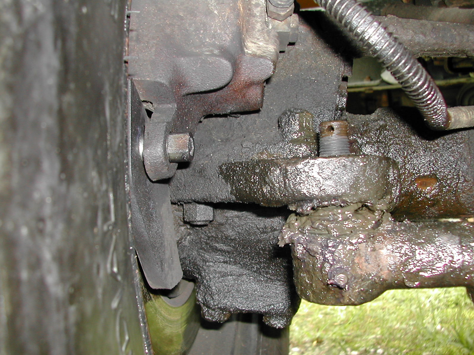
| Photo 1 | Left, driver's side, tie rod end after removing cotter pin and castle nut. Notice wetness of area resulting from liberal dose of penetrating oil to the general area before work commenced... |
| Photos 2-3 | Right, passenger side, tie rod end after removing cotter pin and castle nut. Notice wetness of area resulting from liberal dose of penetrating oil to the general area before work commenced... You also get a decent view of the disc brake setup in this shot. |
| Photo 4 | Passenger side of tie rod after removal from truck. |
| Photo 5 | Driver's side of tie rod after removal from truck. |
| Photo 6 | View of the entire tie rod assembly after removal from the truck. I took a marker and located the ends, bolt hole location and other points of the assembly on the concrete of the floor in order to help assure myself that I had it right when I reassembled the unit with new parts. |
| Photo 7 | Tie rod ends with new grease fittings installed. The new ends as received did not have the fittings in the boxes. |
| Photos 8-9 | Right, passenger side, after reinstalling on the truck, but before greasing. |
| Photo 10 | Left, driver's side, after reinstalling on the truck, but before greasing. |