 1
1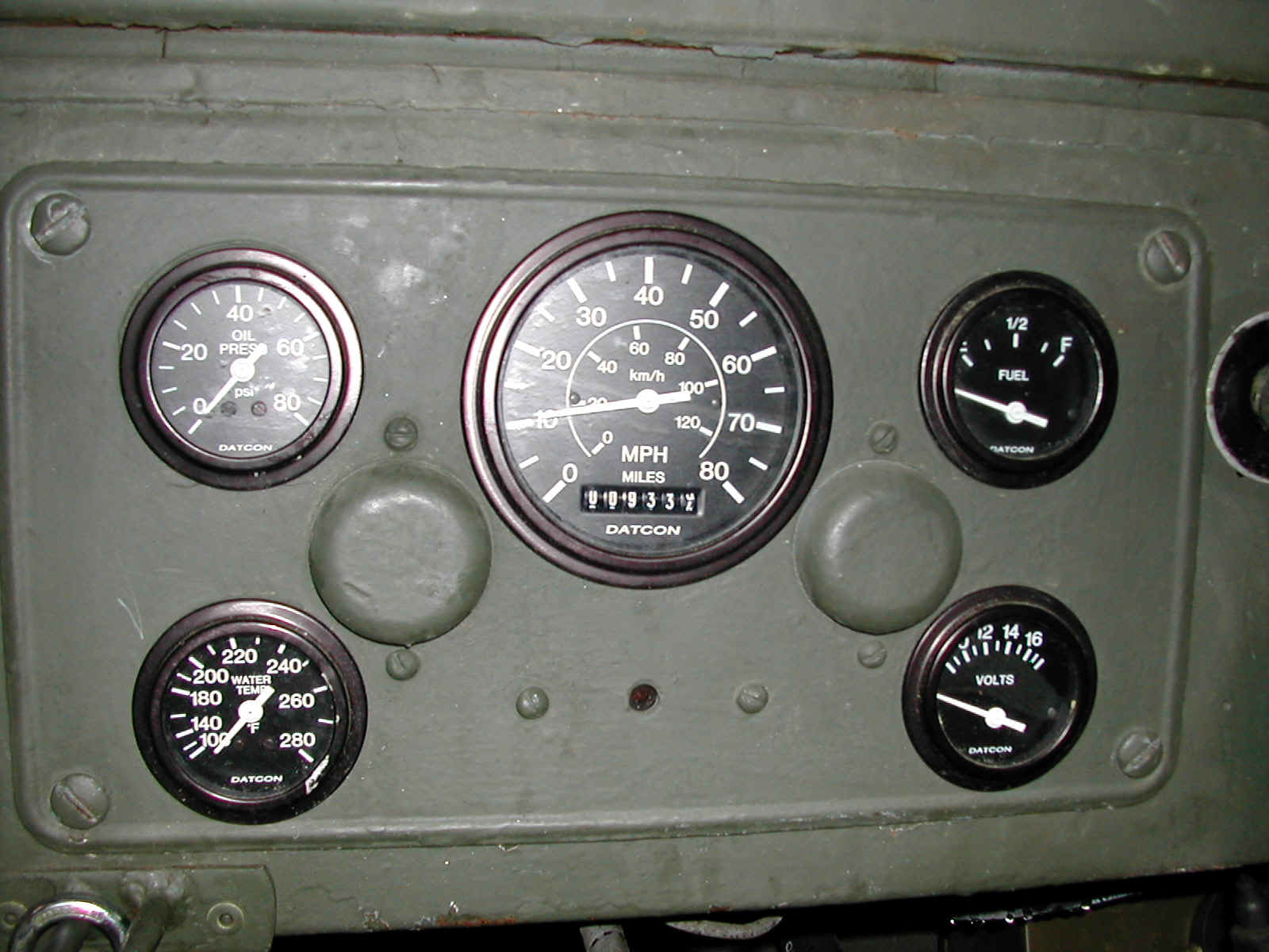 2
2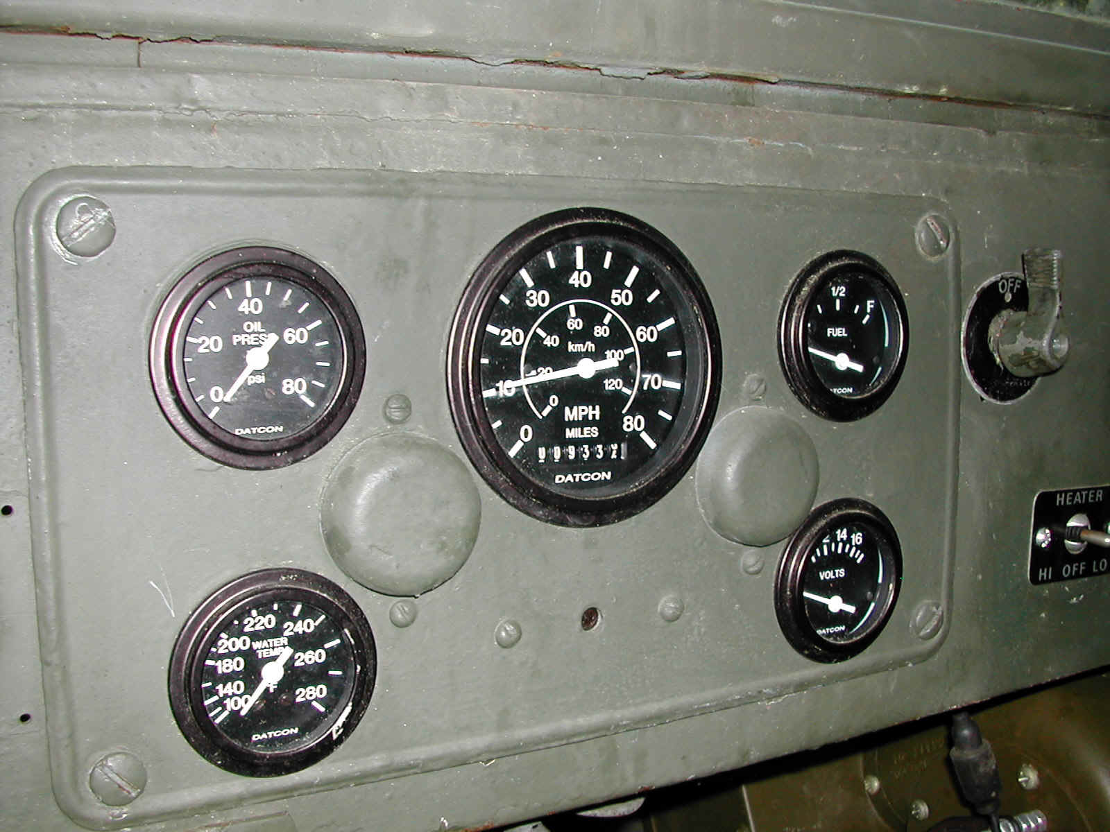 3
3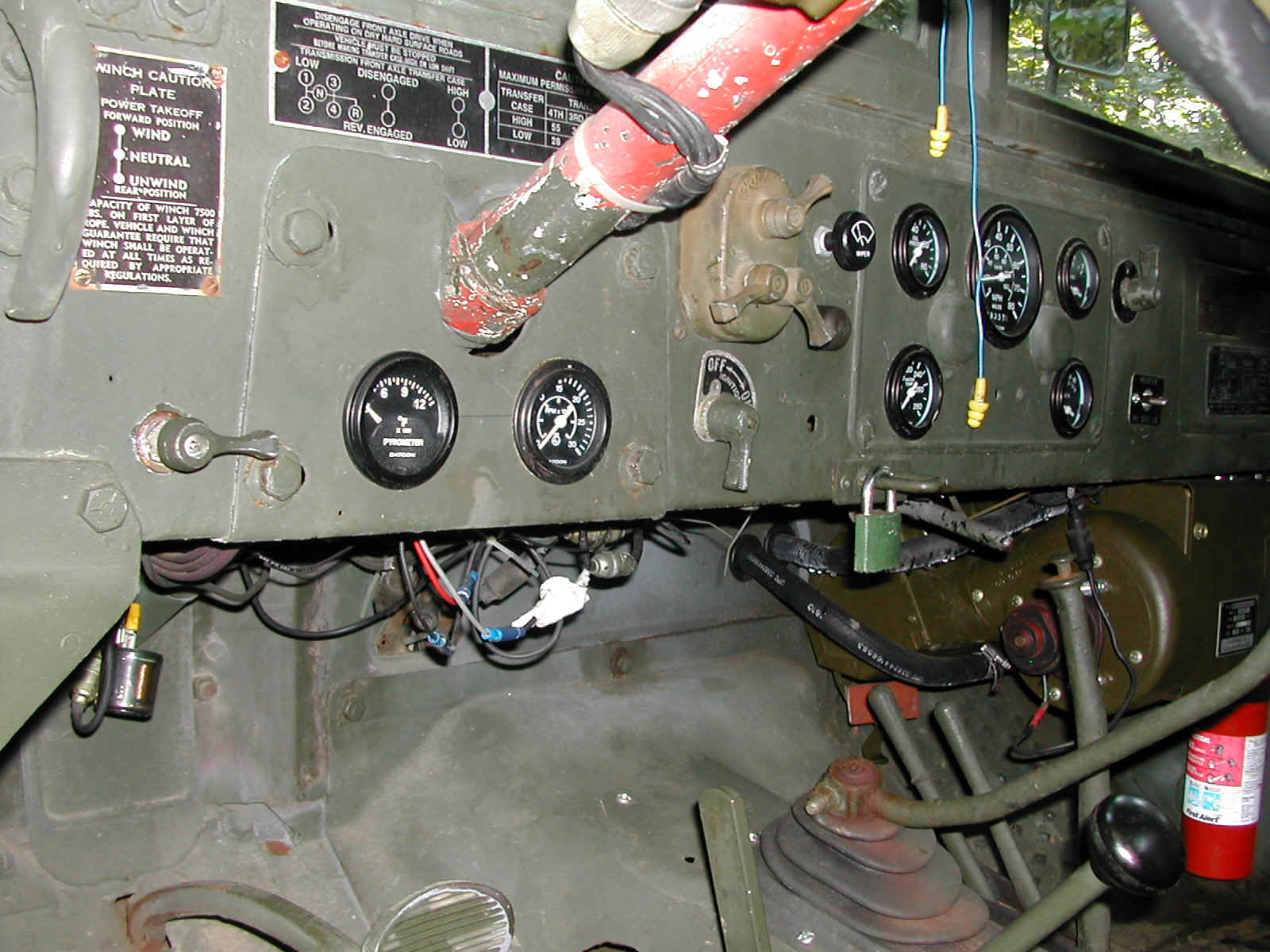 4
4Datcon Gauges
I decided to replace the stock gauges in my '53M37 for several reasons. First, when I replaced the flathead engine that was originally in the the truck with the Cummins, I converted the truck from 24 volts to 12 volts and needed to change the electric gauges. Second, the speedometer only went up to 60mph and the changes to the truck upped the top end to 75mph and its drive cable tended to bread at the bend near the transfer case. Third, the oil pressure gauge had been replaced with an aftermarket unit that did not match the rest of the gauges. Forth, I wanted to add a pyrometer and tachometer to the existing gauges so I could more closely monitor the Cummins' performance.
With all of this in mind, I decided that the best thing to do was to replace the stock gauges with a new set that matched the stock ones as closely as possible while still providing for durability and accuracy. I discovered Datcon gauges while looking at Stewart Warner gauges. Stewart Warner was the OEM supplier to Dodge when the M37 was built, and still supplies a large number of the gauges used in US military vehicles. Unfortunately, I couldn't find a set of gauges in their commercial line that looked correct in the truck. I then noticed that Maxima Technologies which owns Stewart Warner had a second instrument company as part of their corporate identity - Datcon. Datcon supplies gauges to companies like Caterpillar and Komatsu and has a line of gauges that look just like the OEM units in the M37 without the extra National Stock Numbers silk screened on the dials. I also learned that Diesel Equipment Company in Greensboro, where I purchased my electric wiper parts, was a distributor so my mind was made up.
Speedometer
I replaced the stock speedometer and cable with a programmable electric 0-80mph unit
from Datcon since I was exceeding the top end of my existing speedometer after dropping in
the Cummins. I paired the speedometer with a 60-pole pulse generator that screws into the
t-case. The 60-pole pulse generator delivers 30 pulses to the speedometer for each
rotation of the drive tang coming off the t-case. In my situation with the 4.89 gears and
the currently mounted 900x16 tires, I have 800 revolutions of the drive tang per mile, or
24000 pulses/mile. This puts me in the middle of the range available with the speedometer,
so I can vary tire size axle gear ratios and all I have to do is recalculate pulses per
mile and adjust the dip switches in the
speedometer accordingly for an accurate reading. Not only do I get a speedometer that
looks original and has a more useful range (for me), but I eliminate the cable breakage
problem that I used to have at the t-case.
The method for programming the speedometer according to the installation instructions is to attach a pulse counter to the pulse generator and to drive a distance that is a fraction of a mile and multiply the number of pulses obtained by the amount needed to make the distance traveled equal a mile. This gives you the number of pulses per mile and you look this up in the table that comes with the speedometer and set the dip switches accordingly. In my case, I don't have a pulse counter. So I did my pulse per mile determination the old way. I marked spots on a nearby cul-de-sac 52'9.5" apart and then drove my truck between these marks several times while a buddy sat in the back and counted the number of revolutions that the original speedometer cable made. I than multiplied the average number of rotations he counted by 100 to find the number of revolutions per mile. Multiplying the number of revolutions per mile by 30 (the number of pulses per revolution that a 60-pole pulse generator provides) gave me the number of pulses per mile the speedometer would see. I then went to the table and set the dip switches accordingly.
The speedometer is wired with a pair of leads from studs on the back of the head unit to the sender. It makes no difference which stud is attached to which tang on the sender. The lead from the light kit was then attached to the positive stud on the back of the gauge. I ran a jumper from the stock wiring harness positive feed to the instrument cluster (it's a line that comes off the ignition switch) and connected it to the positive stud. I used this stud as a common bus for all the other gauges, so I no longer use the five wire spider that was used with the stock gauges to provide them with power. I also ran a line from a screw on the steering column bracket that I used as a grounding point for other cab item to one of the studs on the speedometer head where the speedometer mounting bracket is attached. I then used this stud as a common ground for all of the gauges just to insure that everything had a really good ground even though everything should ground well through the mounting brackets and the instrument panel.
| Item | Part number | quantity needed |
| Speedometer (0-80mph) | 103644 (12 volt unit, 24 volt available) | 1 |
| Pulse generator | 71266-00 (60 pole unit) | 1 |
| Drive tang | 71274-00 (fits between transfer case and pulse gen.) | 1 |
| Wire | two conductor, 12 gauge multistrand | 8' |
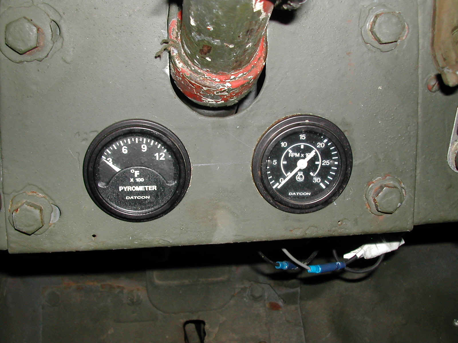
Tachometer
Although its perfectly acceptable to drive a diesel without a tachometer, and I've had a few vehicles that didn't have one, I like knowing what is happening... This is especially true for an powertrain setup that has as many unknowns as mine did (used engine, two transmissions, transfer case, new gear sets with lockers, etc.).
Since I was going to replace the gauges in the cluster anyway, it seemed like a good time to invest in another gauge. In looking at the Datcon catalog and at the Cummins 4BT owners' manual, it looked like the best solution would be an alternator driven tachometer. On these units, the tachometer receives its signal from a pulse generated by the alternator. Since my engine came equipped with a Delco 10SI three wire alternator, it looked like all I would basically have to do was run a wire from the alternator to the tachometer. I spent some time thinking about adapting a M35 gauge panel to the M37, or fabricating one, so that the tachometer could be mounted in the cluster with the rest of the gauges until it occurred to me that I could use one of Datcon's little tachometers and install it along with a pyrometer in the panel that fills in the dash under the steering column.
Since the Cummins 4BT in an automotive configuration redlines at 2500rpm (2800 for a non-EPA certified 4BT), I purchased a tachometer that has a range of 0-3000rpm. I also purchased a light kit for the tachometer since it does not come with a light installed although it is designed to be internally lit. The light kit consists of a bulb holder with a pair of pigtails and a bulb of a voltage and wattage specified by the consumer. I picked the light bulb recommended by the Datcon catalog for a 12 volt application and ordered a pair of kits (one for the pyrometer) only to find out that I would have a months delay in getting the lights since Datcon had to fabricate them for me (I seem to have a knack for ordering items not in stock...).
I cut a pair of 2 1/8" holes in the panel underneath the steering column, and mounted the tachometer in the hole on the right of the steering column. This hole has an unobstructed view whereas the other hole is partially blocked by the turn signal indicator which I figured would be alright for the pyrometer, but not desirable for the tachometer considering my driving habits.
Wiring was accomplished by extending the positive and negative leads on the gauge using insulated crimp but splices and connecting the supply and ground to the speedometer (which acts as a common bus for all of the gauges) using insulated ring connectors. The leads on the light kit where wired the same way, but the positive is connected to a different stud on the speedometer (that is fed off the line that formally fed power to the lights for the original gauges). The sender line was connected to pin R on the alternator.
When I fired up the truck for the first time with the new gauges, the tachometer did
not operate. After chasing the wiring a bit, I finally called Datcon's technical
support and discovered that I needed to install a capacitor in line between the tachometer
and the alternator (conveniently not mentioned on my gauge or alternator literature).
A buddy of mine who works with electronic items on a regular basis donated a 250
volt, 1mfd nonpolar capacitor with an upper operating temp of at least 75 C. It had
monofilament leads, so I cut the 14 gauge multistrand wire running between the tachometer
and alternator and soldered the ends onto the ends of the leads on the capacitor and then
tied the wire leads into a square knot along side the cap case in order to provide some
strain relief. I then wrapped the whole thing thoroughly with electrical tape and
have been enjoying the tachometer since.
| Item | Part number | quantity needed |
| Tachometer (0-3000rpm) | 106474 (12 volt unit, 24 volt available) | 1 |
| Light kit | 100330 (pyrometer light kit 12vdc, 24 volt available) | 1 |
| One Microfarad Capacitor | 1 |
Oil Pressure and Temperature
These two are a little different than the other gauges in that I went with mechanical units instead of electrical gauges with senders. For each of them, an extension was fitted to the lead on the light fixture that was then connected to the positive stud on the back of the speedometer. Jumpers were run from a mounting bracket stud on each of the gauges to a similar stud on the speedometer that served as a common ground bus to insure good grounding of all the brackets.
The oil pressure gauge pitot tube was then attached to the back of the gauge using a compression fitting that is supplied with the gauge. The tube was then routed through the firewall and connected to a pressure port on the driver's side of the engine. Since Cummins has a reinforced flexible rubber line that was very well attached to the block that the donor truck's oil pressure gauge had been attached to, I attached the thin plastic pitot tube from Datcon to the same line using a compression fitting. I then wire tied the fitting between the two lines to the top of the block using an unused accessory attachment bolt hole as a tie point. This serves to keep the oil line from flopping about the engine bay.
The temperature gauge sender line was routed through the same hole in the firewall that the oil pressure pitot tube was routed through. The line was routed down the drivers side of the engine block through some j clips that are attached to the block using the intake manifold retaining bolts that also serve to restrain some of the electrical lines running to the fuel injector pump. The temperature sender is placed in the water outlet neck at the top front of the engine using one of the three 1" holes provided for this purpose and an adapter provided with the gauge.
| Item | Part number | quantity needed |
| Oil Pressure | (Mechanical with 12 volt light kit, 24 volt available) | 1 |
| Temperature | 101321 (Mechanical with 12 volt light kit, 24 volt available) | 1 |
Voltmeter
The voltmeter is a fairly straightforward swap. The gauge is mounted in the same location that the stock unit was mounted, and a jumper was installed between the positive terminal on the back of the gauge and the positive terminal on the back of the speedometer that I used as a common bus. The positive lead on the light was then attached to the positive terminal on the back of the gauge. A short jumper with a ring terminal on one end and a metal military connector on the other was used to connect the signal stud on the gauge to the stock wiring harness fuel sender wire under the dash. Since I am a little leery about the grounding capability of the mounting bracket through the instrument panel, I installed a second jumper between one of the studs where the mounting bracket is attached to the gauge and a common ground stud on the speedometer that was eventually grounded the to truck's body.
| Item | Part number | quantity needed |
| Voltmeter | 101358 (Mechanical with 12 volt light kit, 24 volt available) | 1 |
Pyrometer
Info coming soon!
| Item | Part number | quantity needed |
| Pyrometer | 100510 (12 volt unit, 24 volt available) | 1 |
| Light kit | 100330 (pyrometer light kit 12vdc, 24 volt available) | 1 |
| Sender | 100252 | 1 |
| Lead (wire to sender) | 1 |
Fuel Level
The fuel level gauge is a fairly straightforward swap. The gauge is mounted in the same location that the stock unit was mounted, and a jumper was installed between the positive terminal on the back of the gauge and the positive terminal on the back of the speedometer that I used as a common bus. The positive lead on the light was then attached to the positive terminal on the back of the gauge. A short jumper with a ring terminal on one end and a metal military connector on the other was used to connect the signal stud on the gauge to the stock wiring harness fuel sender wire under the dash. Since I am a little leery about the grounding capability of the mounting bracket through the instrument panel, I installed a second jumper between one of the studs where the mounting bracket is attached to the gauge and a common ground stud on the speedometer that was eventually grounded the to truck's body. The tank sender was a little more difficult to install. The unit that I purchased is a fixed depth sender that looked like it would be a drop in installation, but I had to adjust the holes in the mounting flange of the sender slightly (redrilled a couple) in order for the holes to line up with the studs on the fuel tank. After getting the studs to line up with the holes in the flange in such a manner as to have the float arm pointing directly at the right frame rail when the tank was installed in the truck (3 o'clock position), I installed the sender into the tank making sure to use plenty of fuel resistant gasket sealer around both sides of the new gasket. I then trimmed the metal military style connector off the truck's wiring harness and replaced it with a ring terminal that was attached the stud on the sender.
| Item | Part number | quantity needed |
| Fuel Level (Gas Gauge) | 101347 (12 volt unit, 24 volt available) | 1 |
| Sender | 02301-03 (Fixed for 7" tank depth, will need to adjust holes in flange) | 1 |
| 1 |
2 |
3 |
4 |
Pete's Gauges
Pete at the BigElectric M37 forum took the information above and order up some Datcon gauges for use in a custom instrument panel he fabricated for his M37. The table below shows his parts numbers, costs, and supplier. As with the gauges that I used, they are available from any of the Datcon distributors and are available in both 12 or 24 versions. Pictures of Pete's installation are located below his parts table.
Datcon |
Useage |
||||||
In Stock |
Price |
Description |
Datcon # |
Bezel |
Voltage |
Voltage |
Notes/Questions |
$182.87 |
Speedometer, P-Low, 0-80 mph |
103718.00 |
Polished |
24 |
24 |
||
$2.07 |
Light Kit, 24 Volt |
71224-01 |
|||||
X |
$96.47 |
Pulse Generator, 60 Pole, 7/8"x16 UNS |
71266-00 |
||||
X |
$15.39 |
Pulse Generator Drive Tang |
71274-00 |
||||
Tachometer, 0-4000, Battery Ignition |
103735.00 |
Polished |
24 |
24 |
Just needs light kit |
||
X |
Light Kit, 24 Volt |
71224-01 |
|||||
Tachometer Mounting Cup, 3-3/8 Dia. |
71461-00 |
Black |
|||||
$25.27 |
Fuel, 240-33.5 |
104354 | Polished |
24 |
24 |
Does not work with stock sender, see sender below... | |
X |
$4.00 |
Light Kit, 24 Volt |
06294-00 |
||||
In Stock |
$20.16 |
Fuel Sender |
02301-03 |
M37 stock Sender is 0-30 ohms, this version is fixed for 7" tank depth, will need to adjust holes in flange |
|||
$25.25 |
Oil Pressure, 0-80, 240-33.5 |
104342.00 |
Polished |
24 |
24 |
||
X |
$4.00 |
Light Kit, 24 Volt |
06294-00 |
||||
X |
$22.46 |
Oil Pressure Sender |
02504-00 |
||||
$25.27 |
Water Temperature, Polished, 100-240, DAL |
104346.00 |
Polished |
||||
X |
$4.00 |
Light Kit, 24 Volt |
06294-00 |
||||
X |
$6.50 |
Water Temperature Sender |
02017-00 |
||||
X |
$24.20 |
Voltmeter, 16-36, Colored Dial |
101911.00 |
Polished |
24 |
24 |
|
X |
$4.00 |
Light Kit, 24 Volt |
06294-00 |
||||
$19.57 |
Ammeter, 40-0-40 |
101903.00 |
Polished |
12 |
24 |
Just needs light kit |
|
X |
$4.00 |
Light Kit, 24 Volt |
06294-00 |
||||
Total |
|||||||
$485.48 |
|||||||
Distributor: |
Electrical Sales & Supply |
||||||
340 NE 75th Street |
|||||||
Miami, Florida 33138 |
|||||||
(800) 432-3132 |
|||||||
Email: ESSMiami@aol.com |
|||||||
Fax: 305-754-6398 |
|||||||
Aluminum Plate: |
McMaster Carr # 88895K46 |
||||||
12" x 24" x 1/8" Thk., 5052, $15.71 |
|||||||