Heater Installation
There are two different sets of instructions for installing M151 heat into a M37 on this page from Dave Rowe and from Harris Neil on this page. I didn't follow either set to the letter when I installed heat into my truck, but I found both of them to be of great assistance...
Following are the instructions for
installing a M151 (MUTT Jeep) heater kit into a M37. These instructions are courtesy
of Dave Rowe and include how to install the defroster setup that is part of the kit.
PARTS:
M-151 Heater Installation Kit (1)
Threaded pipe adaptor-female/male (1)
1 ˝" hole saw
6"X6" steel shelf brace
2’ of 2" flexible duct hose
Before starting it is important to inventory all the parts in your heater kit. My kit had an inventory sheet, but no instructions. It is important to check the fit of the various parts, and figure out what you have. Then read through the procedure and see what else you may need in the way of parts or tools.
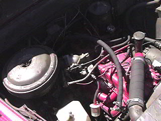
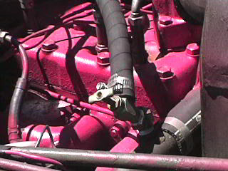
The heater kit has two screw type water valves, a threaded adapter, a length of heater hose, and several grommets. Drain radiator. Remove threaded plug from the upper radiator hose fitting. Screw one of the valves into the threaded adaptor and put it into this hole. (Picture heater_02) On the rear of the head there is a plug marked heater. Remove this plug. This hole is too big for the valve in the kit. Insert the threaded pipe adaptor you bought, screw the second valve into this. (Heater_03) Now you will need to assemble the heater motor and diverter box that attaches directly to it. Set it under the dash about where it will be installed. (heater_1) This will help you place the holes for the hoses. Carefully check placement of the holes for the hoses from both sides. Once you are certain of hole placement use the 1/12" hole saw to cut two holes. Insert a grommet inot each hole. I found it easier to cut from inside the cab. If you place the holes well and watch how you route the hoses then the hose supplied in the kit should suffice, but there won’t be much extra. When passing the hose through the grommets a little liquid dish soap rubbed inside the grommet will make the job easier. Once the hoses are through you are ready to move on to mounting the heater assembley.
As mentioned above, assemble the main duct to the heater motor. It is held on with a couple of screws provided. The air outputs should be toward the firewall.
I used a 6"x6" prefab shelf brace. I got the kind with an integral strut for strength. I attached one side of the brace to the existing attaching tab on the heater core. Once attached I held the assembly in place so that the brace was aligned just inside the front edge of the dash and the end of the heater core was about 1" away from the passenger side kick board. The assembly is heavy and you will need to brace it in place while you mark holes. Mark holes as appropriate through the upper side of the brace (I used two holes). You can insert your mounting hard war to help keep the assembly in place while you mark a hole in the bottom of the glove box to line up with the existing mounting tab on the back of the motor. Mark through the existing tab on the back of the heater core onto the passenger side kick board. Drop the heater assembly and drill the next two holes. I made a spacer to go between the heater core and the passenger side kick board by drilling a hole through a 1" thick piece of oak. Hang the heater by the three top bolts. Getting the bolt in on the passenger side kick board is a little tricky. I found it easier to reach down between the kickboard and outer skin of the truck with a bolt and push it back through the hole. The bolt needs to be short enough get through the hole without hanging up, but long enough to get through the spacer. A long limber arm is handy here. I wish I had them. You can now finish by attaching your hoses.
The heater kit has two diverter boxes and two defroster ducts as well as several lengths of duct hose. I installed the defroster ducts first which made it easier to place the driver’s side diverter box.
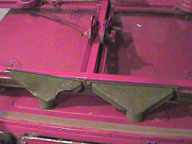
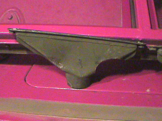
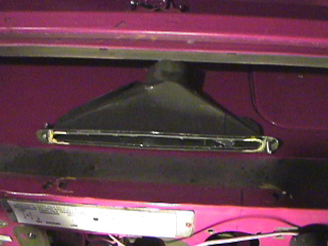
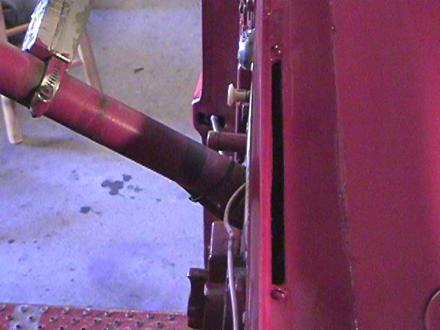
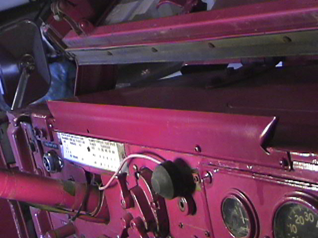
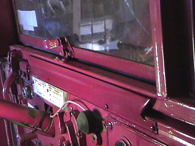
On the driver’s side remove the large plate under the steering column. Remove the four screws that hold the main light switch in place and remove the switch.. Reach up inside the dash and you will feel a channel at the top where the body sections come together. The defroster ducts will fit into this channel. The ducts will go into the channel as shown in (heater_2). Notice the rounded cut out on the driver’s side duct. This is shown more clearly in (heater_3) and is required to clear the light switch. Place the duct up in place in the channel. Marck the edge of the light switch hole on the duct. Take the duct out and cut off the place marked. Cut it a little large. You will need to check the fit by holding the duct in place and replacing the light switch. It may take a little jiggling but it can be done. I patched the hole from the inside of the duct with a piece of aluminum from a soda can and some RTV, something like GOOP or SHOE GOO works good. While the patch is drying hold the other duct up inside the channel (be sure to place it the same way). You will be able to see the right hand end of the duct through the switch hole. Make an alignment mark up the front of the dash to the top. Take the duct out and place it on top of the dash so it is over the channel and aligned with the mark. Now mark the two screw hole and the draw a line around the rubber grommet the seals the duct to the dash. (heater_4) The drill the two mounting holes as marked. The correct attaching hardware is in the kit. The next step is to cut a duct through the dash. I did the first one (driver’s side) with the cutting wheels on my dremel tool. This took a little time and several wheels since this is a double layer of steel. On the passenger side I used my drill with about a 3/8 bit and drilled a series of adjoining holes. This was faster but not as pretty. However the end result is hidden anyhow. (heater_5). Now attach the long round duct hose to the defroster duct and install the modified duct (when dry). Replace the switch. Attach the defrost deflector plate to the front of the dash using hardware (screws) supplied. (heater_6 and heater_7) You can now install the driver’s side diverter box. Attach it to the hose from the duct and to the large square hose that runs over to the passenger side diverter box. Place the diverter box against the firewall near the steering column. This placement is a little tricky and won’t look perfect. You will need to either drill through the firewall and through the mounting bracket on the box, or try to attach it to the steering column with a hose clam. I went through the firewall. (heater_8)
On the passenger side the duct will fit without modification. Move it to the right (up against the left side of the glove box) as far as possible. Once in position follow the same procedures to mark, cut and install as for the driver’s side. The short piece of round hose provided it too thick and stiff to work here. I used a piece of HMMWV heater duct hose, but you should be able to find something similar at your local hardware store. Attach this hose between the passenger side defroster duct and diverter box. The deflector plate will be too long due to the glove box. I cut it off and shaped the end with my Dremel tool using the driver’s side plate as a template. You can make it a lot more basic though.
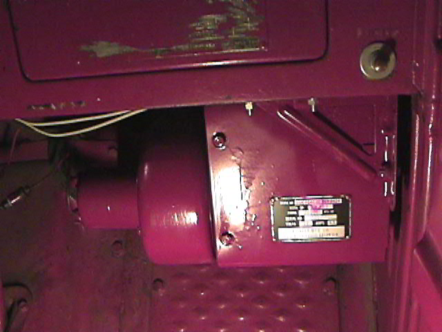
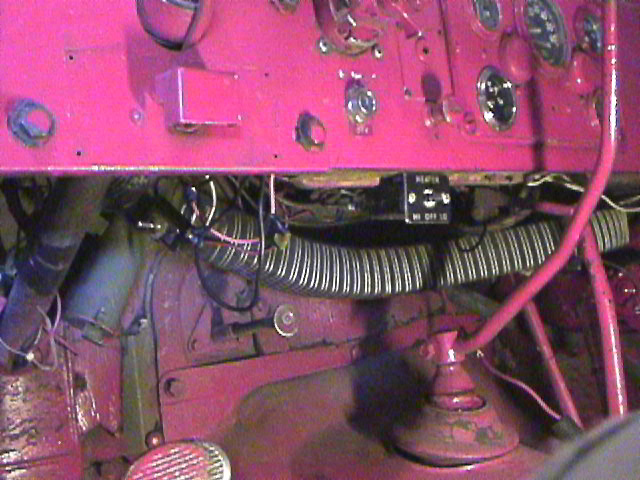
The electrical installation is pretty straight forward. All the parts required are supplied in the kit, except a bracket for the switch. I formed a simple right angle bracket from a spare piece of metal in the kit. The instructions for the electrical installation are the same as in TB9-2855-45 "INSTALLATION OF HOT WATER PERSONNEL HEATER KIT" ON PAGE 11-13. The placement of the heater switch is visible under the dash in (heater_8).
 heater 01 heater 01 |
 heater 02 heater 02 |
 heater 1 heater 1 |
 heater 2 heater 2 |
 heater 3 heater 3 |
 heater 4 heater 4 |
 heater 5 heater 5 |
 heater 6 heater 6 |
 heater 7 heater 7 |
 heater 8 heater 8 |
Good luck with your heater kit.
Contact me at drowe@king.cts.com if you have any questions.
Dave Rowe
Following are the instructions for
installing a M151 (MUTT Jeep) heater into a M37. These instructions are courtesy of
Harris Neil and describe how to install the basic heater (sold seperately from the
rest of the heater kit) into the truck.
Parts List:
1.1, Heater, 24V, (Hunter Mfg. Co., Model #HW-20-2, Stock # NSN2540-00-869-
0424;originally designed for M151
2.1, ˝" NPT brass nipple, 3 inches long, or, if you can find them, 2, 1/2" NPT
to 5/8" I.D. hose brass fittings
3.2, rubber grommets, 1 1/16" I.D.
4.9 feet, 5/8" inside diameter heater hose
5.1,Heater shutoff valve, with outlets for 5/8" hose
6.1, push/pull type valve control cable
7.6, hose clamps (7/8" to 1 1/8" size)
8.2, ľ" x 6" metal straps
9.7, ľ" x Ľ" pan head machine screws, with nuts and lockwashers
10.10, Ľ" fender washers
11.4, Ľ" flat washers
12.1, toggle switch
13.1, "T" tap (to tap into your electrical system)
14.4 feet, 10 gauge stranded electrical wire
15.1, butt splice (a 10 gauge butt splice will plug onto the Packard connection that comes
on the heater)
16.4, cable ties
Pre-installation:
Prior to installation, check your glove box. If it shows any sign of rust or weakness, you
may want to reinforce it by running a
metal strap from the exterior front side (facing firewall) of the box, to the bottom of
one of the bolts that secure the passenger
side hood hinge. I did not do this, and have had no problems.
Installation Instructions:
Take the 3" brass nipple, 1/2" NPT (National Pipe thread), and cut it in half.
Remove two pipe plugs; one from the top, passenger side rear of the engine head (the word
"heater" is cast into the head
adjacent to it) The other from your lower radiator pipe. If the lower radiator pipe has no
fitting (as mine did not) use the fitting
on the top of the elbow atop your water pump. If you have changed the water pump, and the
elbow is no longer there, you will
have to remove the lower radiator pipe, drill into it, thread the half nipple into it,
then solder it. This works, as it is what I had to
do.
Get a 1 and 5/16" hole saw. Drill two holes in the fire wall above, and slightly to
the passenger side of the rear hot water outlet,
where you put the nipple. You will have to drill from the engine side to the passenger
compartment. Triple check your location,
to avoid hitting wiring, speedometer cable, or vacuum line.
Get two grommets (PCV valve grommets are what work) that have the diameter to let
5/8" I.D. heater hose pass through.
Install these in the holes you just drilled.
Work 5/8" heater hose onto the two nipples. It will be very difficult, but it will
stretch enough. Use WD40 or petroleum jelly to
ease it along. Start with a 6' piece from the lower radiator hose, and a 3' piece on the
rear. You will trim to fit when the time
comes.
Get the heater shutoff control, and the push/pull control cable. Install the valve into
the line exiting the rear of the engine. It
should have only enough hose between the top of the engine nipple, and the valve to allow
correct fitment of the clamps. The
control cable can be trimmed to length by removing the inner wire, clipping off the
sheath, and then re-inserting the inner wire,
and clipping it, so approx. 6" extends. install the knob end in the location of your
choice, on the dash. The cable can be fed to
the engine compartment through the same bracket the choke and hand throttle cables come
through, since there should be an
extra space from when the manual PCV control was there. Then attach the end of the control
cable to the valve. Attach the
remainder of the output heater hose to the other side of the valve, then feed both hoses
through the grommets in the firewall. I
routed the return hose (the one hooked to the lower radiator pipe) to the passenger side
of the engine compartment, then
around the rear of the air cleaner. I secured it to the hood support bracket rod with
cable ties. (Just to the rod, not the support
bracket itself of course).
Fabricate two brackets out of the metal straps. These should be 3/4" to 1 1/4"
wide, by 6" long. Bend them 90 degrees, at the
three inch point. Drill one hole in one leg, and attach (using panhead screws, with a flat
washer on either side of the heater
brackets, then a lockwasher, and nut) one strap to each of the holes in the radiator grill
end of the heater, so that they go up
(towards the top of the heater, as determined by the heater data plate). The other end
should point toward the motor end of the
heater. This leg of the bend should be parallel with the top of the heater. Drill two
holes in the other end of the straps, at least 1
and 1/2" from each other.
With the straps installed on the heater, turn the heater upside down, on a sheet of
standard office paper (8.5 x 11) place the
hole in the bracket, near the motor end 1 inch from an 8.5" end of the sheet,
centered between the 11" sides. Align the heater
with the sheet (make it square). Draw marks at each of the holes in the bracket, and
straps. Take the paper, and tape it to the
bottom of your glove box, so the edge with the mark of the motor end bracket is flush with
the driver's side edge of the bottom
of the glove box. The mark should be center between the front and rear of the box. Use a
punch to locate your holes. Remove
the paper, and drill the 5 holes, each 1/4".
Use 5 pan head machine screws 3/4 x 1/4" place a fender washer on each, and drop them
through from the inside of the glove
box. Have someone hold your heater in place, then install a fender washer, lock washer,
and nut on each of the five screws.
Hook your output (from engine through valve) hose to the input line (the longer brass
pipe) of the heater, after trimming to
length. Trim and hook the return hose to the other line.
Use good quality hose clamps at all connections, even those very tight ones at the
nipples.
Use the toggle switch, tapped into the line from your main "On/Off" switch, to
control the blower motor. Since my truck had a
plug where the PCV manual shutoff used to be that is where I put the toggle switch. With a
little hunting, you can find one that
looks very mil spec.
If you have any questions, please email me.
Good luck,
Harris Neil
OMEINV@aol.com